PROVE / Mechanical design
Aeroshell Alignment
Our vehicle’s carbon-fiber aeroshell needed to be centered between the wheels without interfering with the welded chassis, which differed from the CAD model. I designed a measurement and alignment system to locate the body panels on the actual vehicle.
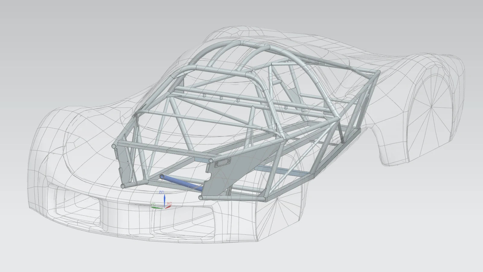
Design decisions
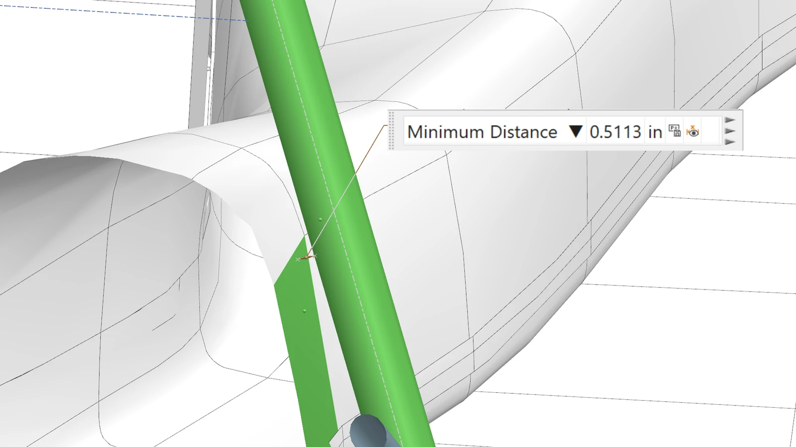
Clearance and measurement requirements
I used the tightest clearance between the aeroshell and chassis to determine the required alignment precision. I compared 3D scanning, tape measurements, and string references against cost, tolerance buildup, and available space before selecting laser distance measurements.
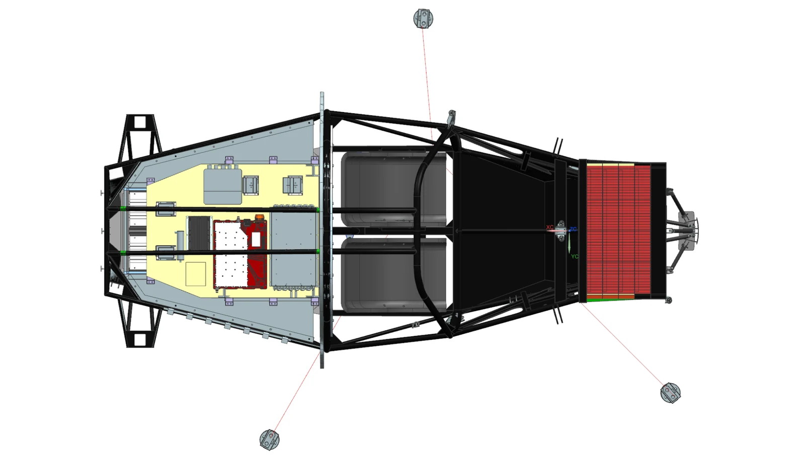
Laser measurement system
I designed a setup using three laser distance measurers to locate the bottom-panel mounting holes in a common reference plane. Referencing the front and rear wheel centerlines would keep the aeroshell centered on the vehicle, while locating the holes in one plane simplified the measurement problem.
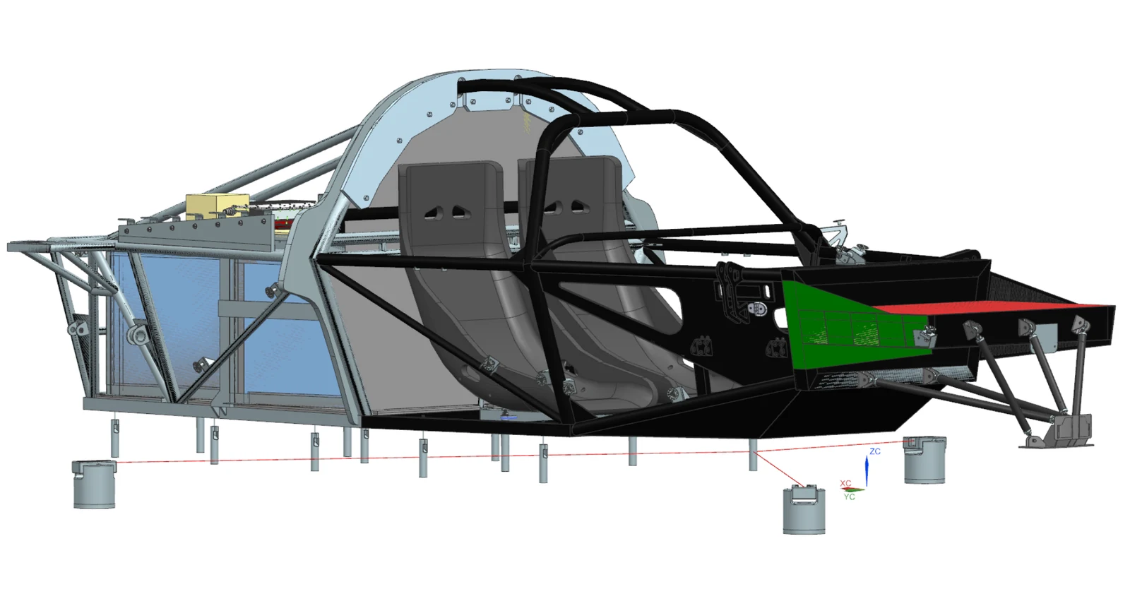
Mount locations and CAD alignment
My workflow allows the mounts to be welded where the physical chassis permits, then measured with the laser setup. Those locations are transferred into Siemens NX to position matching holes in the bottom panel. Once aligned, that panel serves as the reference for assembling the rest of the aeroshell.
Panel joints and fastening design
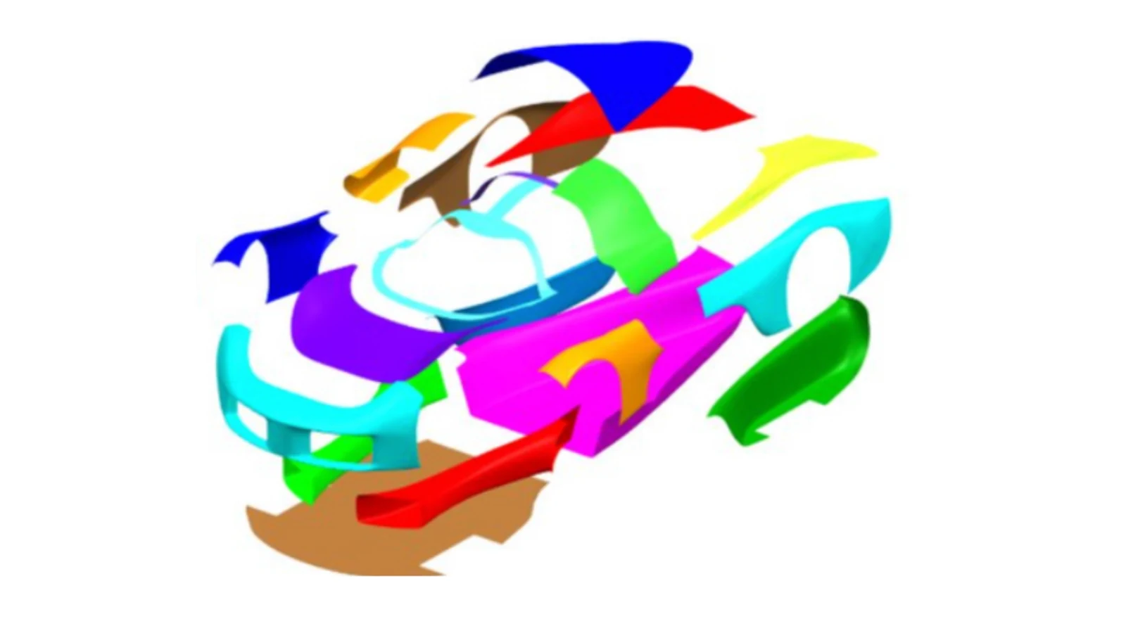
The rest of the aeroshell is then assembled around the bottom panel using elevator bolts bonded to one panel and secured through holes in the adjoining panel. The locations are marked on both panels through indentations in the mold.